
Throughout history, man has never been lack of curiosity about the unknown. The ancients relied on a pair of eyes to observe the sky. With the development of science and technology, people gradually learned to use tools instead of "eyes" to watch everything, such as telescopes and cameras. As objects became smaller and smaller, more sophisticated instruments were invented, such as microscopes. The above "eyes" can not do the task when we need to observe the subatomic particles. Thus scientists create special "eyes" to observe these particles, which are particle detectors. The spark chamber is just one of many "eyes" for subatomic particles.
A spark chamber is a device for detecting charged particles. It was one of the detectors used by early elementary particle physicists to explore the subatomic particles that make up the universe and one of the few detectors that can show the visible motion of cosmic rays. Therefore, spark chambers are widely used in particle physics experiments.
The main purpose of a spark chamber is to observe the motion trajectory of high-energy charged cosmic rays. It enables people to have a visual and intuitive sense of the microscopic particles that cannot be directly observed by our eyes and helps people to have a preliminary understanding of particle physics.
Figure 1 is the spark chamber of Tsinghua University:
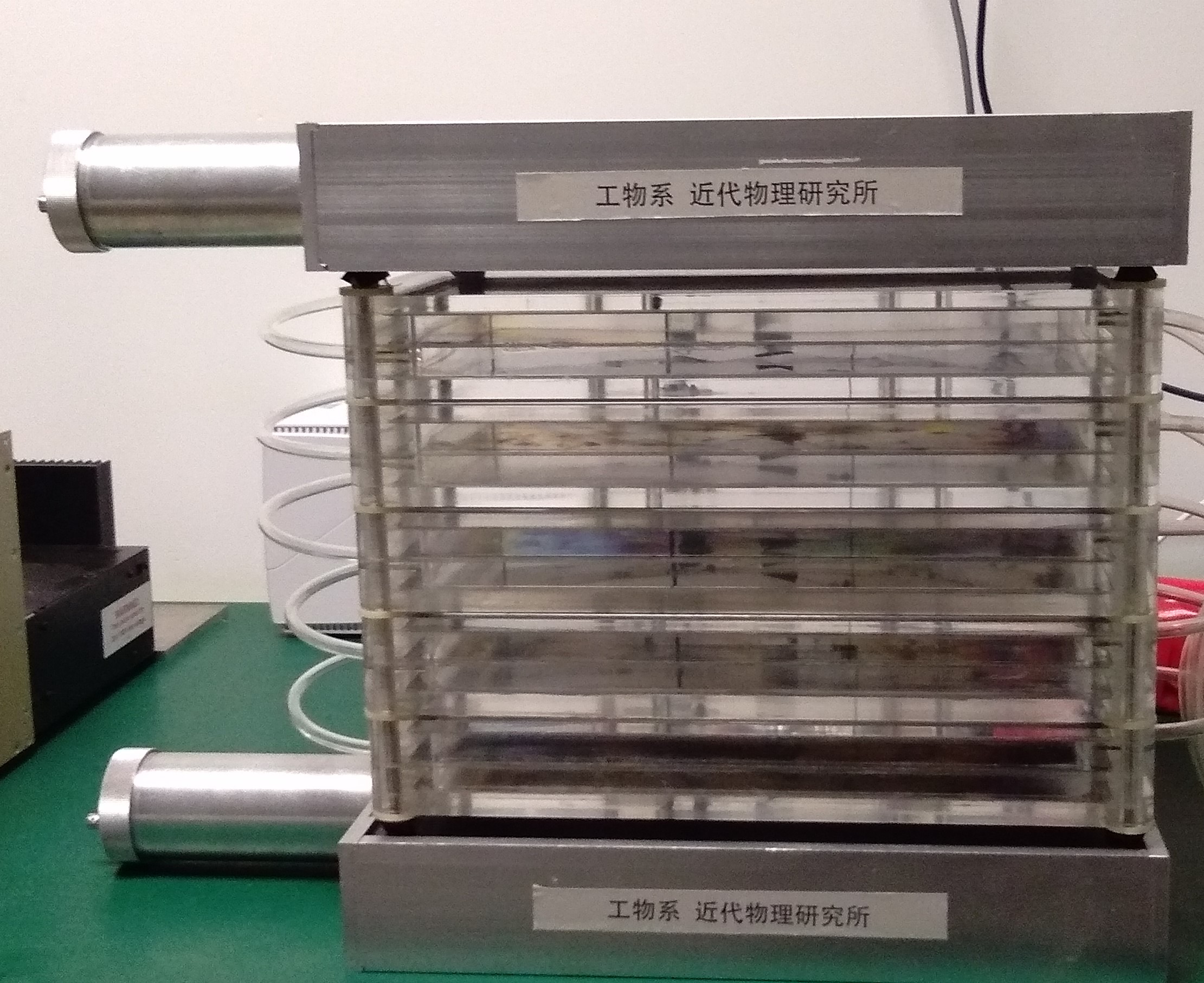
Fig1: Spark Chamber
Spark-chamber detector has a long history and is one of the particle detectors used in the early scientific community. It can be traced back to the late 1950s and was widely used until the early 1960s. Many scientists have made important contributions to the development of spark chambers. The following is a brief list of important historical nodes in the development of the spark chamber. Some references can be found in the appendix:
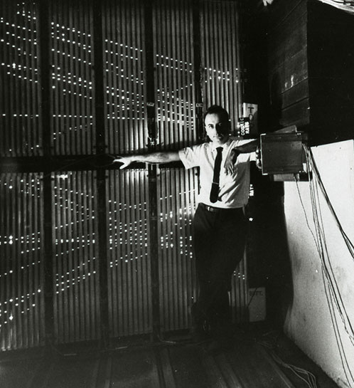
Fig 2:Melvin Schwartz standing next to spark chamber
Before the detailed introduction of Tsinghua's spark chamber, it is necessary to have a brief understanding of the overall working process and principle of the spark chamber:
A spark chamber consists of a pile of conductive plates; the spacing between plates is about 1 cm, and all are immersed in the inert gas. Suppose a charged particle travels through the chamber with a few kV high-voltage applied, the spark chamber can produce bright sparks, showing traces of the charged particle and making certain sounds, like a smaller version of the lightning phenomena in nature, as shown in figure 3.
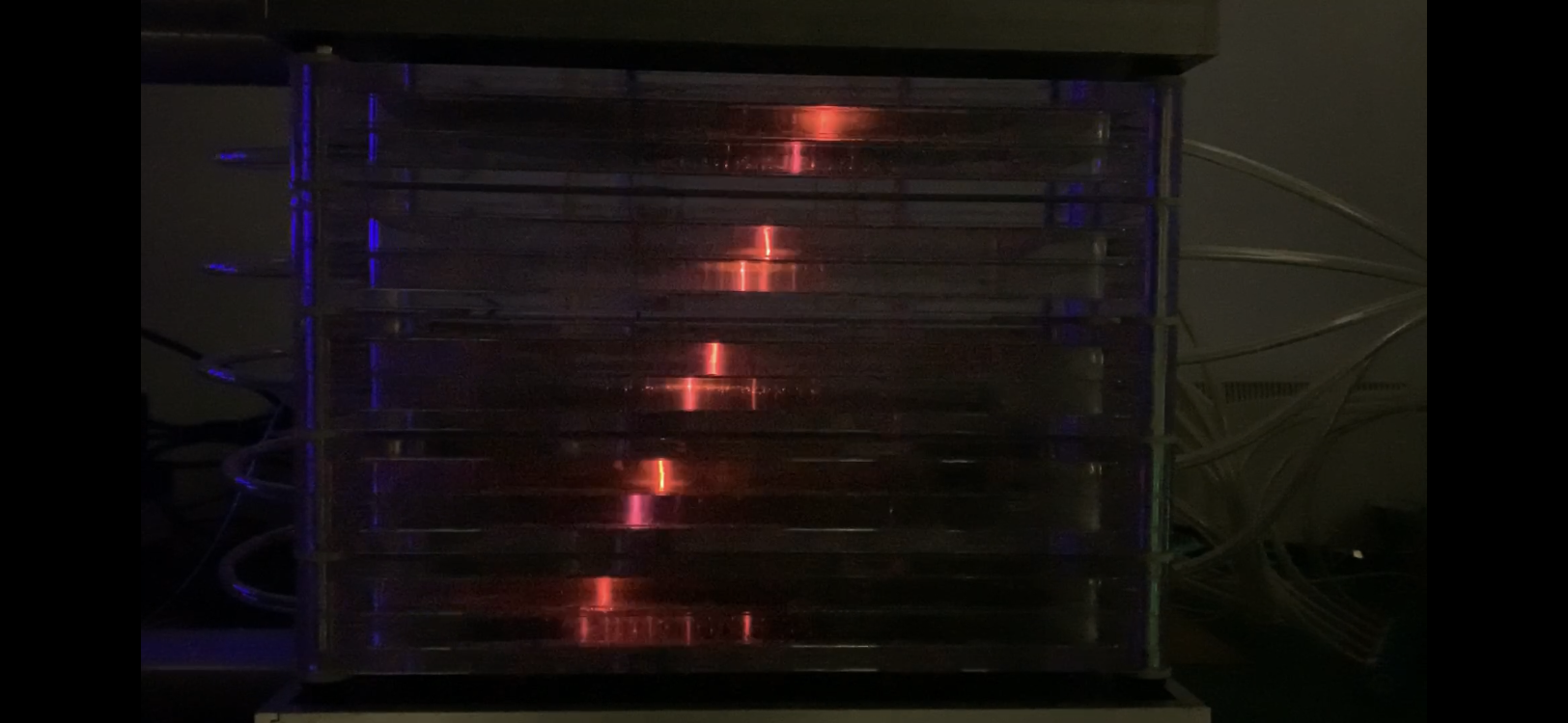
Fig 3: Sparks of spark chamber
The working of a spark chamber lies in how to generate sparks. The method was first proposed by Gremacher in 1935. As shown in figure 4.
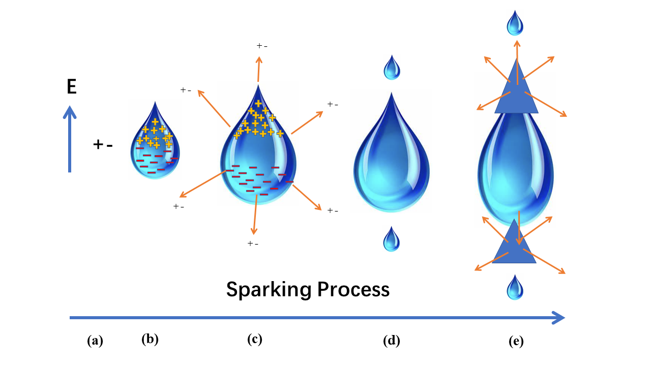
Fig 4:Operating principle
The working process of the Tsinghua spark chamber is shown in Figure 5.
Charged particles passing through the spark chamber will first pass the scintillator at the top of the spark chamber and produce a signal. The particles then go through the spark chamber shell in nanoseconds and ionize the internal gas. Finally, the particles pass through the scintillator at the bottom of the spark chamber. The output signals of the upper and lower scintillator detector are a double coincidence, generating a coincidence signal indicating that a charged particle incident has been detected. The coincidence signal is the input of a high voltage switch which triggers the high voltage to the electrodes. So the sparking process starts, generating deexcitation light, showing the charged particle movement track.
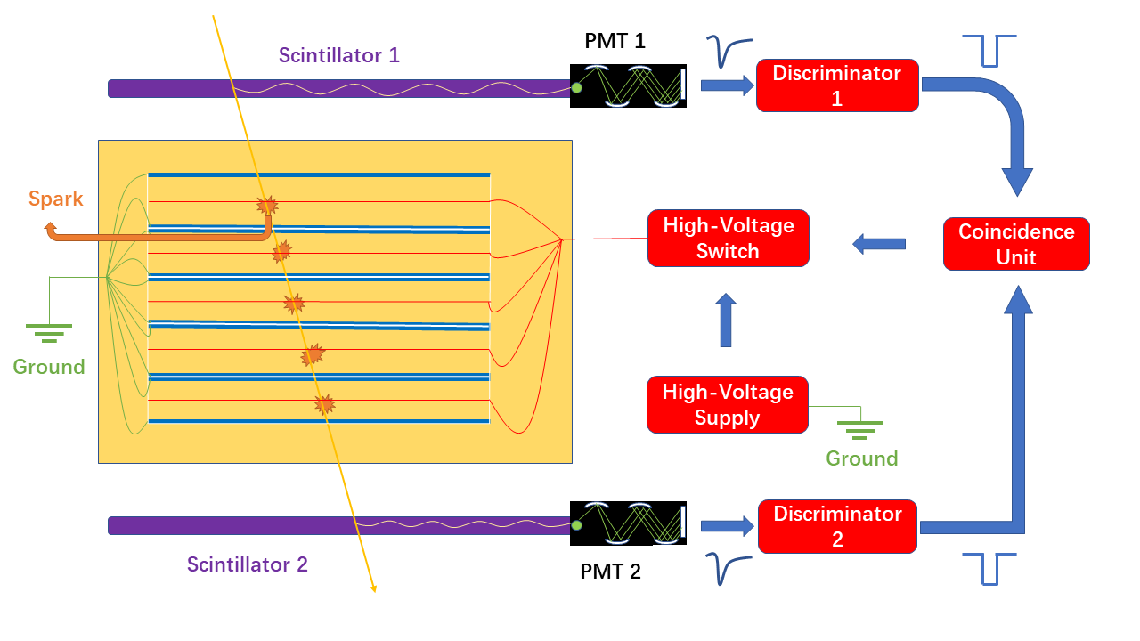
Fig 5:Working scheme of Tsinghua spark chamber
The whole spark chamber of Tsinghua University adopts modular design. Each spark chamber module is mainly composed of three parts. The module structure of the spark room is shown in Figure 6 below:
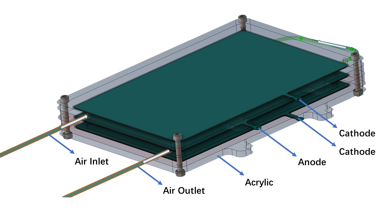
Fig 6:Structure of the spark chamber module
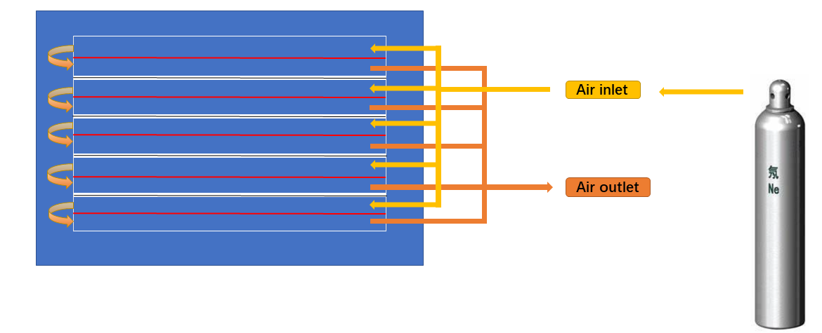
Fig 7:Gas route of spark chamber
The power supply system of the spark chamber needs to meet certain requirements to make the spark chamber work normally. Therefore, a more detailed introduction is made to the electronics part of the spark chamber. The figure 8 below is the overall power supply circuit diagram of the spark chamber:
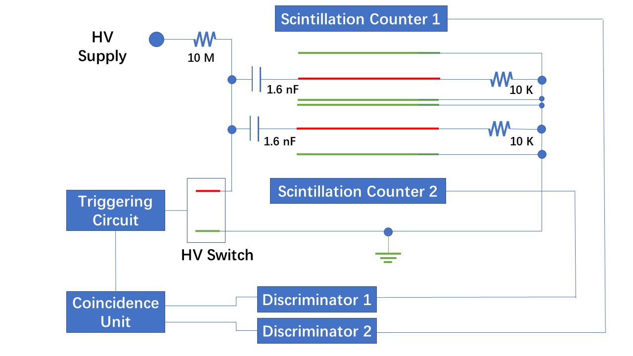
Fig 8: Power supply circuit diagram of the spark chamber
Figure 9 below is the equivalent power supply circuit diagram of the spark chamber. The above requirements can be met through this circuit design and the use of certain electronic components.
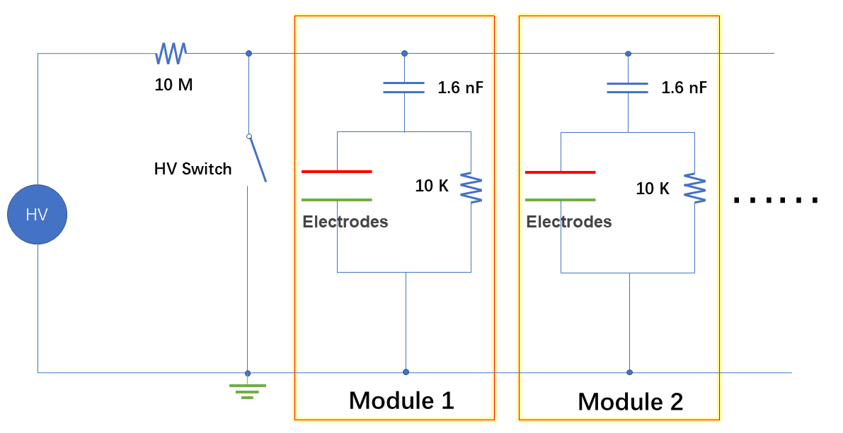
Fig 9:Equivalent power supply circuit diagram
The whole high-voltage trigger circuit logic of the spark chamber is as follows: When particles pass through the top and bottom scintillator detector of the spark chamber, electronic signals are generated through the discriminator. These two electronic models are input into the coincidence module, and the high-voltage switch of electronics is turned on, and the high voltage is output to the metal plates so that the spark discharge process occurs. Because of the small size of the spark chamber, the time for particles to pass through the spark chamber is less than the width of the output waveform of the discriminator, so the upper and lower discriminator signals can be directly matched. But for a large spark chamber, it is necessary to delay the signal of the upper discriminator to ensure the coincidence. The trigger logic also shows that the spark chamber can only detect charged particles passing through the upper and lower scintillators simultaneously, as shown in figure 10.
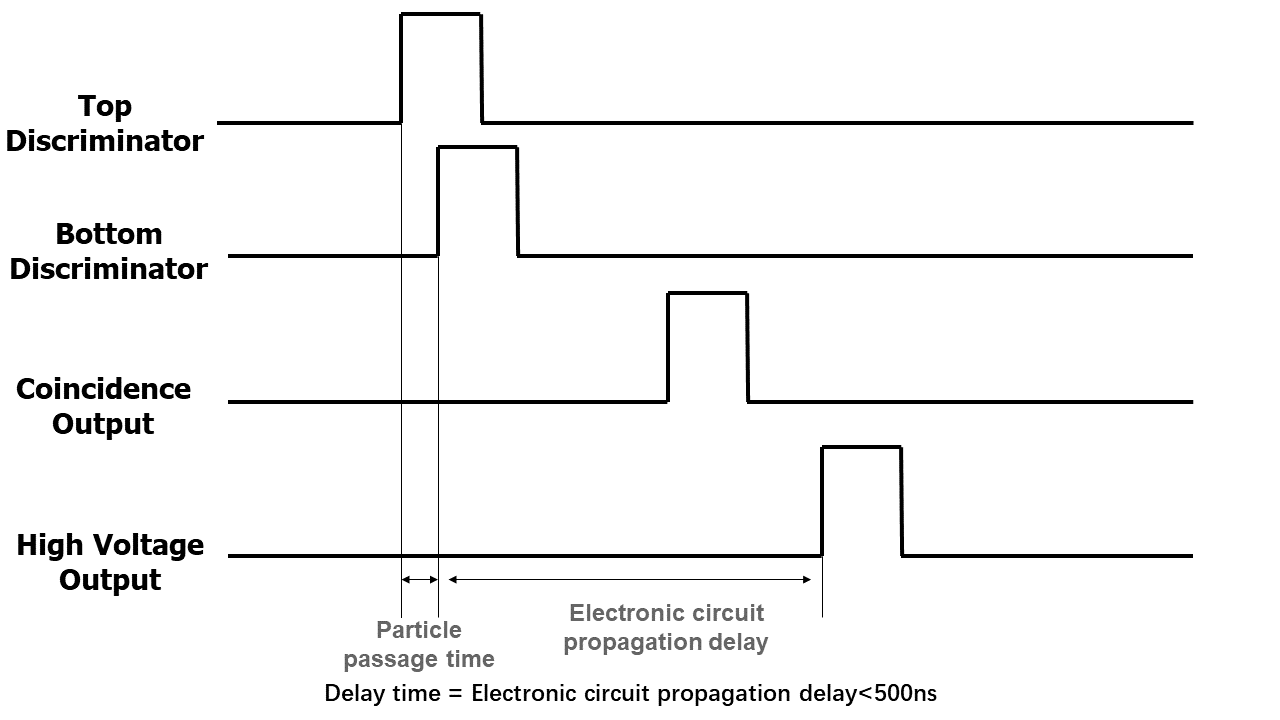
Fig 10:Schematic diagram of spark room power supply time
Due to the special working requirements of the spark chamber circuit, there are certain requirements for the high-voltage power supply circuit and electronic components of each part of the spark chamber:
High voltage power supply: In order to meet the demand of spark discharge, the high voltage power supply needs to be able to provide up to 10 kV voltage. In addition, as there are frequent electrical discharges in the circuit, the high-voltage source needs to be able to provide stable power when the load voltage changes frequently, that is, to handle with capacitive load. When the circuit has frequent pulses, the power supply should not shut down due to self-protection. The spark chamber of Tsinghua University adopts a high-voltage power supply, as shown in Figure 11 below.
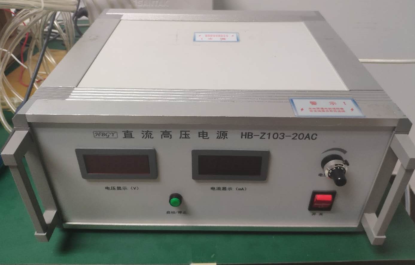
Fig 11:High voltage power
Capacitance and resistance: In order to protect the high-voltage power supply, a 10-megohm voltage protection resistor should be connected in series with the high-voltage source, and 1.6 nF capacitors should be connected at the end of each set of plates, and a 10-kilo-ohm resistor should be connected in parallel. In this way, when the high voltage switch is off, the voltage at both ends of the 1.6-nF capacitor is the same as the supply voltage, and about 1/100,000 coulomb charge is accumulated on the plate; when charged particles going through the chamber, the high voltage switch is closed, in a few nanoseconds the charge on 1.6 nF capacitance discharges quickly, the pulse is passed on to the chamber plates with equivalent capacitance for pF scale, rapid accumulation of about one over one hundred million of the coulomb of charge, make the plate voltage rise rapidly to a certain height, produce the spark discharge.
Since the time interval between high voltage loading and particle penetration is required to be small enough (100-500ns), the high voltage switch needs to respond quickly. Tsinghua university chamber adopted the fast high voltage switch HTS 101-03 made by BEHLKE as shown in figure 11。
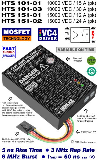
Fig 11:Fast high voltage switch
An oscilloscope and a special high voltage probe (As shown in FIG. 12) are used to measure the high voltage trigger line. The measurement results of circuit time characteristics are shown in Figure. 13 below.The high voltage probe is used to measure the circuit time characteristics when adding 8 kV high voltage. In the figure, yellow signals represent the generation of coincident signal, that is, charged particles passing through the spark chamber, and green signals represent high voltage changes at the two metal plates. It can be seen from the measurement results that the total time delay of the spark chamber in Tsinghua University is within 200 ns, and the pulse rise time is within 30 ns, which meets the requirements of the circuit characteristics of the spark chamber.
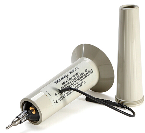
Fig 12:High voltage probe
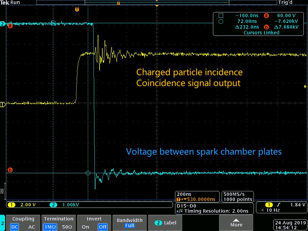
Fig 13:Measured Time Characteristic
The videos linked below illustrate the operation of the spark chamber at Tsinghua University.